In metallic pipelines, corrosion is nature’s constant progression to reduce pipelines to their original oxide state
It is an electrochemical reaction that has four parts: anode, cathode, metallic path and electrolyte. Flange isolation and joint isolation are a means of preventing electrochemical reactions from occurring between two dissimilar metals by breaking the metallic path, or preventing the current in a cathodic protection (CP) from travelling beyond the area intended to be protected by the CP system.
Cathodic protection systems (whether impressed current or passive) are designed to protect primary assets as electrical protection is limited in range. A CP system prevents corrosion by converting all of the anodic (active) sites on the metal surface of a pipeline to cathodic (passive) sites by supplying electrical current (or free electrons) from an alternate source to equalise the potential on the surface of the metal structure.
A typical flange isolation kit will likely perform at least one of three functions over its life: keeping a cathodic protection system captive in a defined area to optimise the effects of the cathodic protection, to stop galvanic corrosion between two dissimilar metals and/or to stop the migration of stray currents through a pipeline.
The effectiveness in achieving flange isolation is dependent on the type of gasket used. Products vary in their ability to isolate dependent upon many variables: proper installation, media type, permeation of the isolation substrate, dielectric value of the isolation substrate, whether the pipeline is hydro-tested, and if the pipeline is exposed to external moisture.
Phenolic isolation gaskets for example are typically cotton fibre, canvas, or paper in an epoxy suspension. The cotton fibre, canvas, or paper can absorb moisture dramatically reducing the isolation properties of the gasket. In addition to a reduction of isolating properties, the compressive strength of the product is significantly reduced which can compromise isolation when installing the gasket and washers (sleeves can be compromised if moisture is present and the flange undergoes side-loading from misalignment).
A number of fibre based gaskets are also available, but face similar issues when exposed to moisture (some fibre based isolation gaskets are even hygroscopic meaning they ATTRACT moisture). This of course can have detrimental effects on isolation as dielectric values can drop significantly in the presence of moisture. Fibre based gaskets can also be crushed with fairly low installation torques. A fibre gasket can crush at approximately 15,000psi gasket stress when dry, but when exposed to a liquid, the crush rating can drop to approximately half of that value.
Glass Reinforced Epoxy (GRE) is perhaps the most common isolation gasket type available. It has a dielectric value typically higher than 500 volts per mil (when dry) and has very little water absorption when immersed in water (with no external pressure). Under a hydro-test, however, the pressure can drive water into the GRE dramatically reducing the isolation capabilities of the product. External moisture is typically not under pressure so it has little effect on the isolation properties of GRE.GRE does have significant permeation issues, so steps must be taken to ensure the design of the product slows down the permeation.
Additionally, the epoxy in GRE is not chemically suitable for a wide range of chemicals including common pipeline products such as H2S or steam, so care must be used when installing these types of isolation gaskets in pipelines containing any of these mediums.
There are isolation gasket designs that utilise PTFE as a sealing mechanism on the Inside Diameter (ID) of the gasket to prevent either chemicals or permeation from entering the GRE. These types of designs would be preferred as they generally eliminate isolation issues with hydro-testing, eliminate the permeation problem and give much better chemical resistance.
Be careful with GRE isolation gaskets with no metal core in higher pressure applications (over 900# class usage). These products can delaminate and fail in high pressures. As counter-intuitive as it sounds, isolation gaskets with metal cores would be a much better choice as long as they have a robust isolating barrier between the metal core and the flange.
Due to the limitations of GRE, a patented PTFE ID isolating gasket has been developed. This design eliminates permeation issues, is more chemically compatible with H2S and steam, and can help with isolation issues following a hydrotest.
The ideal isolation kit will have isolation sleeves that are robust and will withstand the rigors of installation which can be challenging if the flange is misaligned. Mylar sleeves are often used, but a poor choice due to the fact that the material is very flexible and can be easily penetrated by bolt threads with flange side-loading, they can also be difficult to insert into the flange.
G10 and G11 GRE sleeves are the best available products for flange isolation sleeves currently. The sleeves should be the length of the gasket thickness, plus flange thicknesses, plus raised face thickness (if any) plus the thickness of three washers (when two dual washer sets are used per bolt). Please note whether the flanges are raised face to raised face, RTJ to RTJ or RTJ to raised face as the sleeve lengths will be different for each of these flange configurations.
 The washers should be identical and coated with a high dielectric, scratch resistant coating to help prevent a reversal of the washers during installation and damage during installation by the nut rotating on the surface of the non-metallic washers. Ensure that the washer outside diameter is not wide enough so that the washer contacts the flange hub as this can break isolation. Isolation washers must be a unique size so that the sleeve can be accommodated on the inside diameter and the outside diameter does not come in contact with the flange.
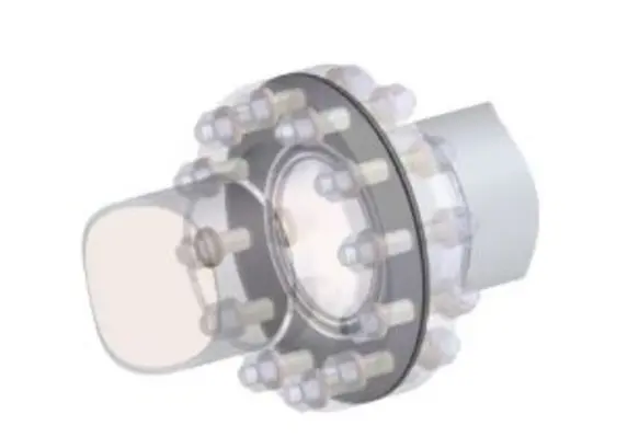
Due to the fact that flange isolation kits are comprised of isolation gaskets, isolation sleeves and isolation washers, here is a diagram of a properly isolated flange:
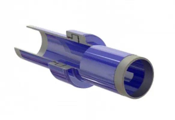
A pipeline can also be isolated by use of an isolating joint. Often called a “Monolithic Isolation Joint” (MIJ) due to the fact that the product looks like a solid block of steel.
This is misleading, however, as there is much more than steel that makes up an MIJ. An MIJ has a path of non-conductive material electrically separating the two halves of the metallic hub.The hub is connected to “pipe pups” (segments of pipe) that are typically the same size and wall thickness as the connecting pipe (see below)
 The ideal MIJ is one that is tested for a number of attributes before ever being installed.In this method, the chance of failure is greatly eliminated.Testing of the welds, the coating, electrical isolation, hydro-testing and pneumatic testing should all be done on each individual MIJ. The MIJ should have the same pressure class rating as a flange in the same pipeline and no part of the MIJ should protrude into the media stream.
Installation of an MIJ must be done properly or damage to the MIJ can result. The MIJ must be lifted with a strap that lifts both sides of the MIJ at the same time and distributes the weight. Lifting the MIJ from one end only can damage the joint and render it useless as an isolating product or can cause it to leak.
An MIJ can often be the best pipeline isolation solution as it removes a number of installation variables that a flange isolating kit (FIK) will have, has a longer isolation path, and can be direct buried (eliminating the need for a vault). MIJs are generally the preferred method for buried pipelines as they do not have nuts/bolts that can corrode when exposed to groundwater.
Isolation is an important piece of corrosion prevention for pipelines and needs to be planned properly to keep dissimilar metals from creating a galvanic cell and to keep cathodic protection within the confines of the area designed to be protected. By selecting and properly installing the correct flange isolation kit and/or monolithic isolation joint, the pipeline should function as designed and corrosion, as well as cathodic protection costs should be kept to an absolute minimum.
By: Tim Hurley, snr. product manager, GPT Industries.


